Disclaimer
WARNING!
RISK OF LETHAL ELECTRIC SHOCK!
THIS OSCILLOSCOPE GENERATES EXTREMELY HIGH VOLTAGES INTERNALLY! THESE HIGH VOLTAGES ARE RETAINED AFTER TURNING OFF THE DEVICE!
DO NOT ATTEMPT REPAIRS UNLESS YOU ARE A QUALIFIED INDIVIDUAL WITH SUFFICIENT KNOWLEDGE AND QUALIFICATIONS IN HIGH VOLTAGE ELECTRONICS! DO NOT OPEN UP THIS DEVICE UNLESS YOU ARE WITH SOMEBODY WHO CAN HELP YOU AND NOTIFY EMERGENCY SERVICES AFTER ACCIDENTS!
Introduction
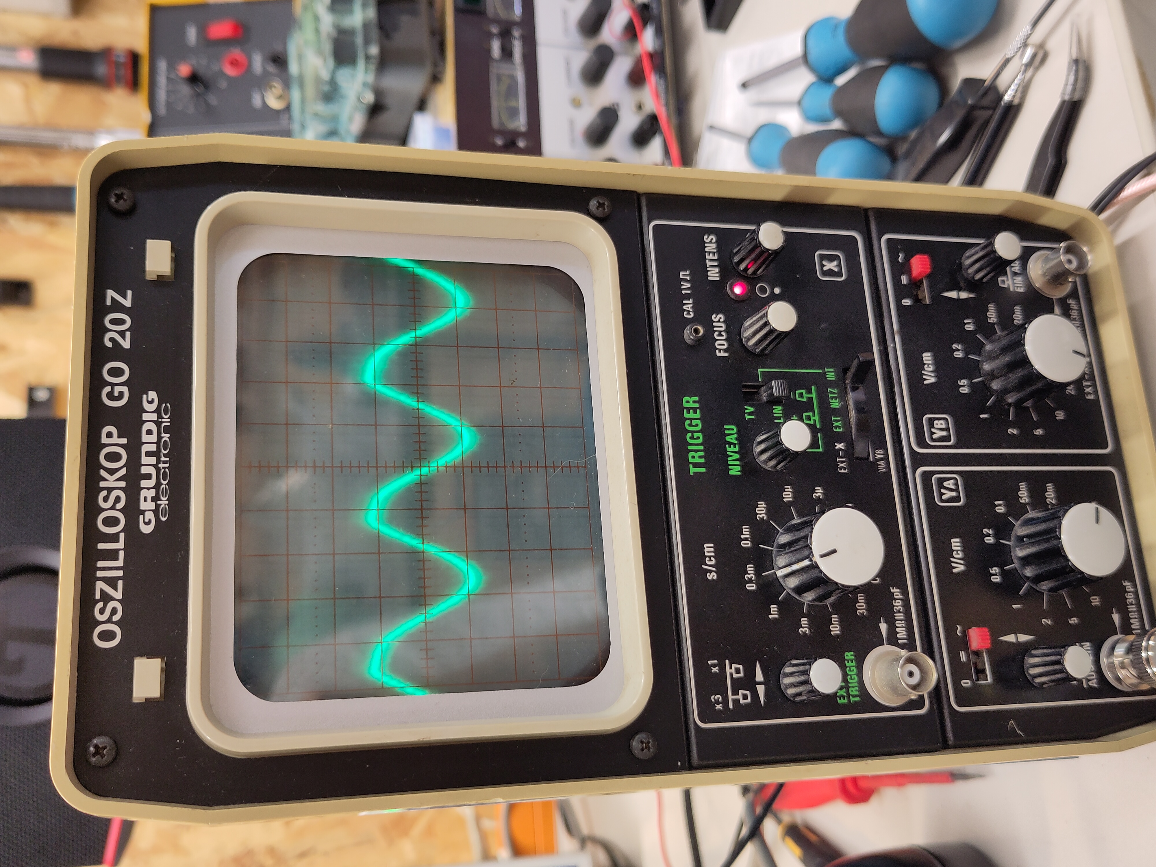
So. Recently, I decided to repair one of my pieces of test equipment: The Grundig GO 20 Z oscilloscope.
This is a 1979 two-channel oscilloscope that goes up to 20MHz. It has a nice vertical construction, a very beautiful colour, the manual includes a full schematic on the last two pages(!) and an interesting filter to properly display television signals. Seems to be in the same family as the GO 15 Z, just with a few smaller differences such as the tube, the knob design and the circuits.
Previous repairs
Before fixing the dead 2nd channel, I went ahead and replaced all of the old electrolytic capacitors and some older HV foil capacitors. Some of the caps were already bulging, so, replacing them was a necessity. You don't want 300V caps to explode. I got most capacitors in the power supply section from Reichelt↗ (external link), and the high voltage foil capacitors from Mouser↗ (external link).
Capacitor list
Vertical (lower) board:
| Reference | Value | Rated voltage | Length | Diameter | Notes |
|---|---|---|---|---|---|
| C117 | 220µF | 25V | 10mm | 5mm | - |
| C119 | 220µF | 25V | 10mm | 5mm | - |
| C217 | 220µF | 25V | 10mm | 5mm | - |
| C219 | 220µF | 25V | 10mm | 5mm | - |
| C125 | 47µF | 350V | L40mm | Ø18mm | Axial |
| C128 | 1000µF | 63V | L40mm | Ø20mm | Axial |
| C126 | 1000µF | 40V | L30mm | Ø16mm | Axial |
| C127 | 1000µF | 16V | L30mm | Ø13mm | Axial |
| C122 | 47µF | 40V | L18mm | Ø10mm | Axial |
| C121 | 47µF | 16V | L15mm | Ø6,21mm | Axial |
| C120 | 10µF | 25V | L10mm | Ø4,5mm | Axial |
| C123 | 2,2µF | 35V | - | - | Tantalum, optional |
| C122A | 2,2µF | 35V | - | - | Tantalum, optional |
| C121A | 2,2µF | 35V | - | - | Tantalum, optional |
Horizontal board:
| Reference | Value | Rated voltage | Length | Diameter | Notes |
|---|---|---|---|---|---|
| C418 | 33µF | 350V | L30mm | Ø18mm | Axial |
| C442 | 33µF | 350V | L30mm | Ø18mm | Axial |
| C421 | 1µF | 63V | H13mm | Ø8mm | Axial, 1% accuracy |
| C601 | 100µF | 6,3V | H13mm | Ø8mm | Axial |
| C420 | 47µF | 16V | H13mm | - | Axial |
| C438 | 0,05µF | 2,5kV | L30mm | Ø10mm | HV foil capacitor |
| C433 | 0,05µF | 2,5kV | L30mm | Ø10mm | HV foil capacitor |
| C431 | 0,025µF | 1,6kV | L20mm | Ø5mm | HV foil capacitor |
| C430 | 0,025µF | 1,6kV | L20mm | Ø5mm | HV foil capacitor |
Fixing the second channel
So, ever since I got this scope, its 2nd channel had been defective. This, of course, bothered me, so, after completing the capacitor replacement, I looked at the channels in more detail. Luckily, the manual includes a very nice and thorough circuit explanation.
Short explanation on analog oscilloscopes: They only have one electron gun. So, displaying two beams (or waveforms), one per channel, is not possible. Instead, the scope switches the channels each time the beam sweeps. So, on the first sweep of the beam, it displays the waveform on channel A, and on the second sweep, the waveform on channel B. Since, on small time scales, the sweep happens rapidly, this switching is not visible to the human eye. On larger time scales (or slower sweeps), the switching happens multiple times per sweep in order to display both beams at the same time.
So, my initial suspicion was that the so-called Zweikanalmodul (two-channel module) had failed. 1979 ICs aren't the freshest after all. However, I thought some more and realized that the Zweikanalmodul also generates the square wave signal for the calibration port, and that worked fine. So, I reconsidered.
Here's the 2nd channel part of the circuit. The first channel looks identical.
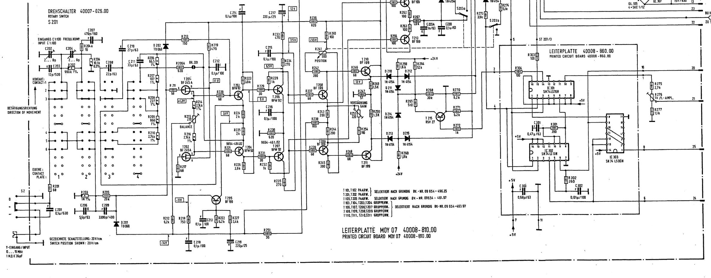
We can see that the signal passes through a bunch of transistor stages, before finally ending up on the output switching stage. D210, D212, D213 and D215 act as electronic diode switches.
Quick explanation on diode switches: When pin 14 of IC301 is high, T215 conducts, pulling its collector to GND potential. This means the voltage potential on the cathodes of D214 and D211, according to the voltage divider formed across R264, R265 and R268, is:
$U_{CH} = 24V \times \frac{R265||R268}{R264+(R265||R268)} = 24V \times \frac{501Ω}{12kΩ+501Ω} \approx 0,96V$
This means the diodes D211 and D214 now suddenly have a voltage differential of roughly 23V across them. 24V on the anodes over the current limiting resistors R259 and R260, and 0,96V on the cathode on the divider. They are forward biased. This means that they conduct, pulling the anodes of the switching diodes D210, D212, D213 and D215 down to 0,96V too. Those diodes are now reverse biased against the signal rail (which sits at 13V, on the emitters of T210 and T211), which means they don't conduct and block the signal.
If pin 14 is low, T215 blocks. This removes one parallel component, R265 at 510Ω, from the resistor and the divider voltage becomes:
$U_{CL} = 24V \times \frac{R268}{R264+R268} = 24V \times \frac{30kΩ}{30kΩ+12kΩ} \approx 17,1V$
This means the Diodes D211 and D214 now have a voltage differential of roughly 6,9V across them. They are, again, forward biased. This means that they conduct, pulling the anodes of the switching diodes down to 17,1V. Those diodes are now forward biased against the signal rail, which, again, sits at 13V. This means they conduct and let the signal pass through.
So, I applied a basic low voltage sine to the input and measured the signal on the emitters of T210 and T211 first, to check if the electronic switches were working properly. Had there been a failure in it, I should've been able to see the signal on those emitters.
Sadly, no signal there. So, I had to check the amplifier section further to the front. I took out the horizontal board for measuring (no active components at this stage so no need to power the board) and measured the gate of T201. The signal, coming from the biasing network, should've been present there. Oddly enough, no signal.
So, I did a test even further near the input and checked if the input BNC connector was good. It was. I measured a bit further down the road and noticed the signal was starting to disappear across R205, which was weird. I did a few more tests.
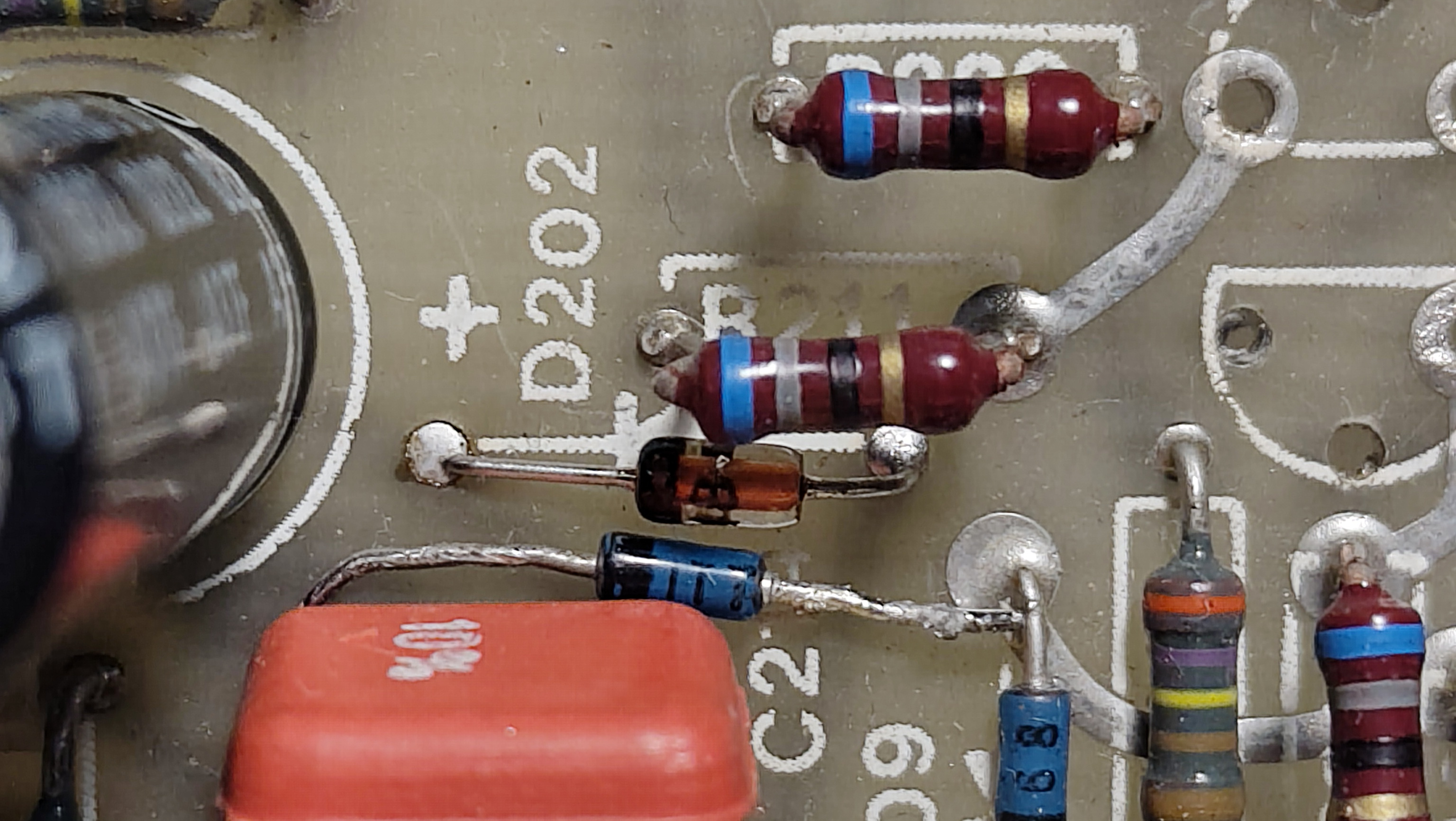
Diode D202 was the culprit. At some point in time, it stopped being good at being a diode and started being good at being an 8Ω resistor. Practically a dead short pulling the input stage at the gate of T201 high to the 12V power supply rail, drowning out the weak input signal's amplitude. This diode was previously used to protect the input section of the oscilloscope from extremely high voltages.
I replaced the diode with a generic 70V 1N4448 and the 2nd channel started working again.
Here's a picture of the old ITT diode and the newly soldered 1N4448 diode: